Air leakage in grinding circuits causes 8-10% output loss, 10-12% higher power consumption, and drying capacity reduction. The most effective approach combines pressure monitoring for early warning, ultrasonic detection for pinpointing leaks, and targeted repairs prioritized by impact, followed by preventive maintenance to stop recurrence.
1. Recognizing Air Leakage Symptoms
| Indicator | What It Means | Impact |
|---|---|---|
| Abnormal pressure readings | Negative pressure drop >10% from baseline | Reduced classification efficiency, material carryover |
| Excessive fan power consumption | Circulating fan energy use spikes (e.g., +8.6 kWh/t) | Higher operating costs |
| Dust emissions | Unusual dust clouds at joints/connections | Environmental violations, equipment wear |
| Temperature fluctuations | Outlet temperature drop (45-55°C instead of ideal 60-70°C) | Poor drying, product quality issues |
| Oxygen level increases | Kiln tail O₂ >7% (ideal 5-7%) | Combustion inefficiency, heat loss |
| Product fineness inconsistency | Uneven particle size distribution | Quality control failures |
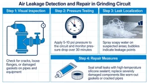
2. Detection Methods (Step-by-Step Implementation)
2.1 Preliminary Inspection (No Tools Needed)
- Listen: Check for hissing/whistling, especially during low-noise periods
- Feel: Run hands along connections; leaks often feel cold (adiabatic cooling)
- Visual: Look for dust streaks, rust patterns, or loose fasteners
2.2 Basic Detection Techniques
- Soap Bubble Test (best for accessible joints):
- Mix 1 part liquid soap + 4 parts water
- Apply with brush to suspect areas (flanges, valves, seals)
- Bubbles = leak confirmed
- Ideal for low-pressure systems; avoid high-temperature surfaces
- Smoke Test (for hard-to-reach areas):
- Use non-toxic smoke generator
- Introduce into circuit while running
- Observe smoke escaping at leak points
- Works well for negative pressure systems
2.3 Advanced Detection Technologies (Most Effective)
Ultrasonic Leak Detection (Gold Standard)
- 工作原理: Detects high-frequency turbulence from escaping air (20-100 kHz)
- Procedure:
- Set detector to 40 kHz (typical for grinding circuits)
- Scan suspect areas (use headphones for noisy environments)
- Mark leaks with numbered tags
- Quantify leak size using dB reading vs. distance
- Advantages: Pinpoints leaks within ±1 cm accuracy, works on live systems, detects micro-leaks (0.01 mm)
- Best for: Vertical roller mill seals, classifier connections, ball mill discharge ends
Pressure Decay Monitoring (System-Wide Assessment)
- Isolate section of circuit (close valves)
- Pressurize to 0.2-0.5 bar above operating pressure
- Monitor pressure drop over 15 minutes
- >5% pressure loss = significant leakage
- Calculate leak rate: Q = (ΔP × V) ÷ (Δt × P₀)
Negative Pressure Differential Test (for closed circuits)
- Install precision MEMS pressure sensors at key points
- Compare internal vs. external pressure (target: -50 to -200 Pa)
- Sudden pressure rise indicates air ingress
2.4 Specialized Detection for Common Leak Points
| Equipment | Critical Areas to Check | Recommended Method |
|---|---|---|
| Vertical Roller Mill | Roller seals, feeder locks, discharge chutes, pipe flanges | Ultrasonic + smoke test |
| Ball Mill | Trunnion seals, discharge end, manhole covers, diaphragm joints | Pressure decay + soap test |
| Air Classifier | Rotor housing, soft connections, classifier wheel seals | Ultrasonic + visual inspection |
| Ducting System | Flanges, expansion joints, valve stems | Soap test + pressure monitoring |
3. Common Leak Points & Root Causes
3.1 Vertical Roller Mill Leakage Hotspots
- Worn roller seals (primary cause): Degraded silicone/PTFE rings lose elasticity
- Loose pipe connections: Poorly torqued bolts on mill-dust collector ducts
- Inefficient feeder locks: Segmented wheel feeders with incorrect gaps
- Flawed discharge systems: Single-flap valves jamming, open chutes
- Weak seal structure: Traditional flat seals failing under vibration/temperature changes
3.2 Ball Mill Leakage Sources
- Trunnion seal failure: Radial/axial misalignment between rotating/fixed parts
- Diaphragm joint deterioration: Loss of flexibility from material fatigue
- Manhole cover gaskets: Compression set from repeated heating/cooling
- Discharge end air infiltration: Poor sealing allowing false air entry
3.3 Classifier & Duct Leaks
- Soft connection failures: Short rubber joints, undersized standard clamps
- Classifier wheel seal gaps: Wear from dust abrasion
- Flange gasket issues: Incorrect material selection for high-temperature environments
4. Repair Techniques (Prioritized by Impact)
4.1 Emergency Repairs (Minimize Downtime)
- Sealant Application (for small leaks <0.5 mm):
- Clean surface with isopropyl alcohol
- Apply high-temp sealant (e.g., Loctite 5980, Belzona 1212)
- Cure per manufacturer instructions (typically 24 hours)
- Best for pipe joints, small cracks, and valve stems
- Clamp Reinforcement (for soft connections):
- Replace standard clamps with heavy-duty, wide-body double clamps
- Ensure soft connections have sufficient length (min 150 mm) for movement
- Tighten to manufacturer torque specs (usually 45-60 N·m)
4.2 Intermediate Repairs (Scheduled Maintenance)
- Seal Replacement (most effective for rotating equipment):
- Roller seals: Upgrade to wave-type silicone seals for better elasticity
- Trunnion seals: Install labyrinth or pneumatic sealing systems
- O-rings: Choose material by environment:
- NBR (Buna-N): General purpose
- Viton (FKM): High-temperature (up to 200°C)
- EPDM: Steam-resistant (avoid oils)
- Flange Reconditioning:
- Remove old gasket, clean flange faces with wire brush
- Install high-temperature gaskets (aramid fiber or metal-reinforced graphite)
- Torque bolts in cross-pattern sequence to specified values (typically 80-120 N·m)
4.3 Major Repairs (Shutdown Required)
- Welding Repairs (for cracked housings/ducts):
- Use low-hydrogen electrodes (E7018) for high-stress areas
- Preheat to 100-150°C for thick sections (>10 mm)
- Post-weld heat treatment to reduce residual stress
- Seal System Upgrades:
- Ball mill discharge end: Install NCB-type improved air seal with spring-loaded graphite packing
- Vertical mill roller seals: Implement labyrinth + pneumatic dual system
- Feeder locks: Replace with rotary feeders with adjustable gap control
- Discharge System Redesign:
- Replace flap valves with non-powered material curtain valves using system pressure for automatic sealing
- Install double airlock valves for critical material transfer points
5. Step-by-Step Repair Implementation Plan
Phase 1: Preparation
- Isolate the system: Close upstream valves, depressurize to 0 bar
- Lockout/tagout: Follow safety protocols to prevent accidental startup
- Gather materials: Prepare replacement seals, gaskets, tools, and safety gear
Phase 2: Leak Assessment & Prioritization
- Tag all leaks with numbered tags indicating:
- Location (e.g., “VRM roller #3 seal”)
- Leak size (small/medium/large)
- Estimated airflow loss (m³/min)
- Priority (1 = critical, 2 = important, 3 = routine)
- Prioritize repairs:
- Priority 1: Large leaks (>5 m³/min), safety hazards, or those causing >5% pressure drop
- Priority 2: Medium leaks (1-5 m³/min) affecting efficiency
- Priority 3: Small leaks (<1 m³/min) to be fixed during scheduled maintenance
Phase 3: Execution (By Leak Type)
| Leak Type | Repair Procedure | Tools Needed |
|---|---|---|
| Seal failure | 1. Remove old seal2. Clean groove (remove burrs)3. Install new seal (lubricate with compatible grease)4. Verify proper seating | Seal puller, groove cleaner, torque wrench |
| Loose connections | 1. Tighten bolts in cross pattern2. Replace damaged gaskets3. Apply thread locker (Loctite 243) for vibration-prone areas | Torque wrench, gasket scraper |
| Cracked housing | 1. Grind crack to V-shape2. Preheat area3. Weld with proper technique4. Post-weld grind and inspect | Angle grinder, welding machine, dye penetrant kit |
| Soft connection issues | 1. Replace short connections with longer versions (min 150 mm)2. Install heavy-duty double clamps3. Ensure proper alignment | Utility knife, clamp tool, measuring tape |
Phase 4: Post-Repair Verification
- Pressure test: Re-pressurize system to operating level, monitor for 30 minutes
- Ultrasonic re-scan: Confirm no residual leaks
- Performance validation:
- Check pressure stability (±2% variation acceptable)
- Monitor power consumption (should decrease by 8-12%)
- Verify temperature recovery to baseline levels
6. Preventive Maintenance (Stop Leaks Before They Start)
6.1 Routine Inspection Schedule
| Interval | Inspection Focus | Action Items |
|---|---|---|
| Daily | Pressure/temperature monitoring, visual checks | Log readings, report anomalies |
| Weekly | Critical seals (roller, trunnion), clamp tightness | Tighten loose connections |
| Monthly | Full ultrasonic scan of all circuits | Tag new leaks for repair |
| Quarterly | Gasket condition, soft connection integrity | Replace worn gaskets |
| Annually | Complete system pressure decay test, seal replacement | Overhaul high-wear components |
6.2 Long-Term Prevention Strategies
- Upgrade sealing systems:
- Install labyrinth + air purge for roller mill trunnions
- Use metal-reinforced gaskets for high-temperature flanges
- Implement pressure-monitored seal systems with automatic alerts
- Design improvements:
- Specify longer soft connections (150-200 mm) for all ducting joints
- Install double-seal arrangements for critical rotating components
- Use torque-controlled bolt tightening during installation
- Training & Documentation:
- Train operators to recognize leakage symptoms
- Create leak repair SOPs with before/after photos
- Maintain a leak history database to identify recurring issues
7. Cost-Benefit Analysis & ROI
| Repair Action | Typical Cost | Energy Savings | ROI Period |
|---|---|---|---|
| Seal replacement (4 roller seals) | $1,500-2,500 | 3.8 kWh/t (e.g., 2,000 t/day = 7,600 kWh/day) | 2-3 months |
| Ducting flange repair (10 joints) | $800-1,200 | 5-7% fan power reduction | 1-2 months |
| Classifier seal upgrade | $2,000-3,000 | 8-10% capacity increase | 3-4 months |
| Full system leak repair | $5,000-8,000 | 10-12% total power savings | 4-6 months |
Final Implementation Checklist
✅ Detection: Complete ultrasonic scan + pressure monitoring
✅ Documentation: Tag all leaks with location, size, priority
✅ Repair: Address high-priority leaks first, verify repairs
✅ Prevention: Schedule routine inspections, upgrade sealing systems
✅ Validation: Monitor pressure, power, and temperature for 1 week post-repair
By following this comprehensive approach, you can reduce air leakage by 60-80%, recover 8-10% lost production capacity, and cut energy costs by 10-12% while improving product quality and extending equipment life.