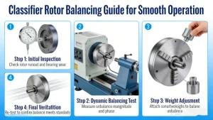
To achieve smooth operation, classifier rotors require dynamic balancing (two-plane) for long rotors and static balancing for short, disc-like designs, with a target balance grade of ISO G6.3 to G2.5 depending on operating speed. The process includes pre-inspection, measurement, correction (add/remove mass), verification, and post-maintenance to maintain balance.
1. Understanding Classifier Rotor Imbalance
Classifier rotors (common in mineral processing) fail when the mass center doesn’t align with the rotational axis, causing centrifugal forces proportional to the square of rotational speed.
| Imbalance Type | Description | Correction Needed | Classifier Application |
|---|---|---|---|
| Static | Single-plane imbalance, rotor “rolls” to heavy spot when stationary | One-plane balancing | Short, disc-shaped rotors (L/D ≤ 0.5) |
| Couple | Two-plane imbalance creating a moment, no static effect | Two-plane balancing | Longer rotors (L/D > 0.5) with blades/vanes |
| Dynamic | Combination of static + couple imbalance | Two-plane balancing | Most industrial classifiers (spiral, turbo, air) |
Symptoms of unbalance:
- High vibration at 1× rotational frequency (radial > axial)
- Increased bearing temperatures and accelerated wear
- Noisy operation and premature mechanical failure
- Phase angle instability at operating speed
2. Balancing Preparation & Safety
Pre-balancing checklist:
- Clean thoroughly: Remove dust, buildup, and debris (main cause of imbalance in service)
- Inspect components: Check for cracks, bent shafts, worn bearings, or damaged blades/vanes
- Verify alignment: Ensure shaft/bearing alignment before balancing
- Safety first: Lockout-tagout (LOTO), PPE, and secure work area
Required tools:
- Vibration analyzer with phase measurement
- Balancing kit (trial weights, adhesive, drill for removal)
- Laser tachometer or optical phase sensor
- Dial indicators for runout checks
- Balancing software (optional, for complex rotors)
3. Balancing Methods for Classifier Rotors
Shop Balancing (Recommended for New/Rebuilt Rotors)
- Mount rotor on precision balancing machine (soft or hard bearing)
- Enter parameters: mass, diameter, correction radius
- Spin to operating speed (or 70–100% of max)
- Measure vibration amplitude and phase at two planes
- Calculate correction masses using influence coefficients
- Add/remove mass and recheck until within tolerance
Field Balancing (For In-Service Rotors)
5-Step Field Balancing Procedure:
- Initial measurement: Run rotor at operating speed, record vibration at both bearings (amplitude + phase)
- Trial weight run: Add known mass at a known angle, remeasure
- Calculate correction: Use vector analysis to determine required mass and position
- Apply correction: Add/remove mass at calculated position
- Final verification: Run again to confirm vibration within limits
Single vs. Two-Plane Balancing
- Single-plane: For rotors with L/D ≤ 0.5 (e.g., small fan-like classifiers)
- Two-plane: For longer rotors (L/D > 0.5) with blades/vanes; corrects both static and couple imbalance
4. Step-by-Step Balancing Execution
Phase 1: Baseline Assessment
- Mount vibration sensors at two bearing planes (90° to shaft, radial direction)
- Run rotor at operating speed (or critical speed if flexible)
- Record:
- Vibration amplitude (mm/s or μm)
- Phase angle (relative to reference mark)
- Rotational speed (RPM)
Phase 2: Correction Calculation
Use influence coefficient method (most common for classifiers):
- Add trial weight (Wt) at known angle (θt) on one plane
- Re-measure vibration (A2, φ2)
- Calculate influence coefficient:
plaintext
α = (A2∠φ2 – A1∠φ1) / Wt∠θt
- Determine required correction mass:
plaintext
Wc∠θc = -A1∠φ1 / α
- Repeat for second plane if two-plane balancing
Phase 3: Mass Correction Techniques
| Method | Application | Advantages | Best Practices |
|---|---|---|---|
| Mass Addition | Most classifiers | Quick, reversible | Use calibrated weights (steel/lead), secure with high-temp adhesive or bolts; error <5% of calculated value |
| Mass Removal | Cast rotors, metal blades | Permanent, no added parts | Drill/mill at “heavy spot”; remove minimum material to maintain structural integrity |
| Mass Shifting | Adjustable components | No material change | Relocate existing weights/vanes symmetrically |
Critical correction rules:
- For two-plane balancing, correct opposite planes (180° apart)
- Weights must be securely fastened to prevent detachment during operation
- Mark all correction locations for future reference
Phase 4: Verification & Acceptance
- Run rotor at operating speed post-correction
- Check vibration levels:
- Target: ≤ 2.8 mm/s (ISO G6.3) for general classifiers; ≤ 1.0 mm/s (ISO G2.5) for high-speed units
- Reduce vibration by ≥ 80% from initial levels
- Confirm phase stability across operating speed range
- Document results (balance report, weight locations, vibration data)
5. Special Considerations for Classifier Rotors
Unique Classifier Challenges
- Blade wear: Uneven erosion changes mass distribution; inspect and replace worn blades before balancing
- Material buildup: Process dust can create dynamic imbalance; implement regular cleaning schedule
- Thermal effects: Hot process air can cause shaft bow; balance at operating temperature if possible
- Assembly errors: Misaligned blades/vanes are a common cause of imbalance; verify symmetry before balancing
ISO Balance Quality Standards (ISO 21940-11)
| Classifier Type | Operating Speed | Recommended Balance Grade | Maximum Permissible Vibration |
|---|---|---|---|
| Low-speed (≤1000 RPM) | 300–1000 RPM | G6.3 | 2.8–6.3 mm/s |
| Medium-speed (1000–3000 RPM) | 1000–3000 RPM | G2.5 | 1.0–2.8 mm/s |
| High-speed (>3000 RPM) | >3000 RPM | G1.0 | ≤1.0 mm/s |
6. Maintenance to Preserve Balance
Post-balancing best practices:
- Regular inspections: Check for blade wear, material buildup, and loose components
- Scheduled cleaning: Remove process dust every 200–500 operating hours
- Vibration monitoring: Trend data to detect imbalance early
- Balancing after major maintenance: Rebalance after blade replacement, bearing change, or shaft repair
- Root cause analysis: Investigate sudden imbalance to prevent recurrence
7. Troubleshooting Persistent Imbalance
| Problem | Likely Cause | Solution |
|---|---|---|
| Vibration remains high after balancing | Incorrect correction plane selection | Re-evaluate and use two-plane balancing for long rotors |
| Imbalance returns quickly | Material buildup | Implement more frequent cleaning; consider anti-stick coatings |
| Vibration varies with speed | Rotor is flexible (operating near critical speed) | Balance at operating speed or perform modal balancing |
| Phase unstable | Misalignment or bearing issues | Correct alignment and replace worn bearings before balancing |
Final Recommendations
- Prioritize dynamic (two-plane) balancing for most classifier rotors (L/D > 0.5)
- Clean thoroughly before any balancing procedure
- Target ISO G6.3 minimum; use G2.5 for high-speed or critical applications
- Combine balancing with regular maintenance (cleaning, blade inspection, alignment checks)
- Document all balancing activities for traceability and future reference
By following these steps, you’ll ensure smooth operation, extend rotor life, reduce maintenance costs, and improve process efficiency.