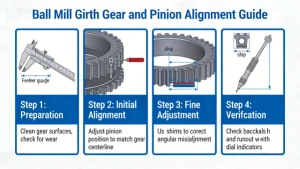
Aligning the girth gear (large gear) and pinion (small gear) is critical for smooth operation, minimal wear, and stable power transmission of the ball mill. Misalignment causes gear tooth pitting, scoring, vibration, and even equipment damage. Below is a step-by-step professional alignment procedure for both initial installation and on-site adjustment.
1. Preparatory Work (Mandatory First Step)
1.1 Safety & Site Preparation
- Shut down the mill completely: Cut off the main power supply, hang “No Startup” warning signs, and lock the control cabinet to prevent accidental startup.
- Clean the gear surfaces: Remove oil, grease, dust, and metal debris from the tooth surfaces, gear pedestals, and adjusting shims. Dirty surfaces will lead to inaccurate measurements.
- Stabilize the mill: Lock the mill cylinder in a fixed position (avoid rotation during alignment) and ensure the foundation is free of settlement.
1.2 Tool Preparation
Prepare precision tools for measurement and adjustment:
- Dial indicators (for radial/axial runout measurement)
- Feeler gauges (for tooth side clearance check)
- Precision level (for horizontal alignment of gear pedestals)
- Red lead or blueing agent (for contact pattern inspection)
- Shims (thin steel plates, for fine-tuning center distance)
- Jacks or hydraulic jacks (for moving the pinion bearing pedestal)
- Tape measure/caliper (for measuring center distance and gear dimensions)

2. Core Alignment Steps
The alignment includes two key parts: radial alignment (center distance) and axial alignment (tooth contact pattern). Radial alignment ensures the gears mesh at the correct center distance, while axial alignment ensures the contact spot is on the correct part of the tooth surface.
2.1 Step 1: Radial Alignment (Correct Center Distance)
The goal is to make the center distance between the pinion shaft and girth gear shaft meet the design standard, and ensure the tooth side clearance is uniform around the gear circumference.
- Measure the center distance:
- Use a dial indicator to measure the distance between the pinion shaft and girth gear shaft (or use calipers/tape measure for rough measurement). Compare with the design value (e.g., 1500mm for a large ball mill).
- The allowable deviation is usually ±0.5~1.0mm (varies by mill size; refer to equipment manual).
- Check tooth side clearance:
- Insert feeler gauges between 3~4 evenly distributed tooth surfaces (e.g., at 0°, 90°, 180°, 270° of the girth gear). Measure the clearance between the pinion tooth and girth gear tooth.
- The design tooth side clearance for ball mill gears is typically 0.2%~0.3% of the module (e.g., 0.4~0.6mm for a module 2 gear). All measured points should be within the tolerance range.
- Adjust the center distance:
- If the center distance is too large/small or the side clearance is uneven, adjust the pinion bearing pedestal:
- Add/remove thin shims under the pinion bearing base to move the pinion horizontally (radial direction).
- Ensure the shims are fully fitted (no gaps) and the bearing pedestal is tightened with anchor bolts after adjustment.
- If the center distance is too large/small or the side clearance is uneven, adjust the pinion bearing pedestal:
2.2 Step 2: Axial Alignment & Contact Pattern Inspection
The goal is to ensure the gear teeth mesh in the middle of the tooth width (no bias to tooth top/tooth root or left/right side). This is done via the contact pattern method.
- Apply blueing agent:
- Coat the working surface of the pinion teeth with a thin layer of red lead (or blueing agent) to leave marks on the girth gear teeth during meshing.
- Perform meshing trial rotation:
- Rotate the mill cylinder slowly (manually or via low-speed motor) to make the pinion and girth gear mesh 2~3 full rotations.
- Check the contact pattern:
- Observe the contact marks left on the girth gear teeth. The ideal contact pattern should meet the following standards:
Position Ideal Contact Range Unqualified Condition Tooth width 50%~70% of the tooth width (centered) Bias to tooth top/tooth root/side Tooth height 40%~60% of the tooth height (middle area) Too close to tooth top/tooth root
- Observe the contact marks left on the girth gear teeth. The ideal contact pattern should meet the following standards:
- Adjust axial position:
- If the contact pattern is biased: Loosen the anchor bolts of the pinion bearing pedestal, and use jacks to move the pinion axially (left/right) to adjust the meshing position.
- After adjustment, re-coat the pinion teeth and repeat the trial rotation until the contact pattern meets the standard.
3. Post-Adjustment Verification
- Recheck all parameters: Re-measure the center distance, tooth side clearance, and contact pattern to confirm they meet the design requirements.
- Tighten all fasteners: Secure the pinion bearing pedestal, girth gear bolts, and mill foundation bolts with specified torque (refer to equipment manual).
- No-load test run: Start the mill for 1~2 hours of no-load operation. Monitor:
- Vibration of the pinion shaft and mill cylinder (vibration amplitude ≤ 0.15mm for large mills).
- Noise level (no abnormal knocking or gear meshing noise).
- Temperature of bearings and gearboxes (temperature rise ≤ 40°C, final temperature ≤ 80°C).
4. Key Notes & Maintenance Tips
- Allowable deviation standards: Strictly follow the ball mill manufacturer’s technical manual—different mill diameters (e.g., 2.4m vs. 4.8m) have different alignment tolerances.
- Wear compensation: As the gear teeth wear during operation, the tooth side clearance will increase. Recheck alignment every 6~12 months, and adjust if the clearance exceeds 1.5~2 times the initial value.
- Avoid over-tightening: When tightening bolts, use a torque wrench to prevent pedestal deformation, which will cause secondary misalignment.
- mill shell deflection consideration: For large ball mills, the cylinder will deflect slightly under load. When aligning, properly pre-adjust the pinion position to compensate for this deflection (consult the manufacturer for pre-adjustment values).